Computer with Win 10 and all Set Up files already Installed
Propeller Activity Board (PAB) or Propeller Microcontroller Module (FLiP)
USB Cable to connect PAB to Computer (USB to USB mini-B) or
for FLiP (USB to USB micro-B connector)
Propeller Tool installed on Computer
Components:
Resistor - 100 Ohm 1/4 W
LED Yellow
LED Red
Jumper - M/M 50mm (2")
AWG24 Yellow
Jumper - M/M 50mm (2")
AWG24 Black
Breadboard, with Power Strips (only if FLiP is used)
Objective:
Turn LED on – assigning I/O pin direction and output state
Synchronized LED on/off signals – event timing based on a register that counts clock ticks
Introduction:
Most microcontroller applications involve reading inputs, making decisions, and controlling outputs.
They also tend to be timing-sensitive, with the microcontroller determining when inputs are
monitored and outputs are updated.
The LED circuits in this section will provide simple outputs.
It should be remembered that the LED represents any possible device that can have two binary
states that is ON (LED lit) and OFF (LED not lit).
The LED
circuits will provide a simple and effective means of monitoring Propeller I/O port outputs and event
timing.
While this section’s LED example applications might seem rather simple, they make it
possible to clearly present a number of important coding techniques that will be used and reused in
later sections.
Project #4-1
LED on with Direction and Output Register Bits
The first project will be to use the Propeller microcontroller to turn LED ON.
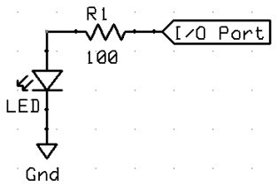
The circuit that will be used is that shown in Fig. 3-7a with I/O connected to
P26.
Fig 3-7a LED Indicator
If you are using Propeller Activity Board (PAB) the yellow
or amber LEDs are already connected to
P26 and P27.
If you are using Propeller FLiP Microcontroller Module (FLiP) the green
LEDs are already connected to
P26 and P27.
The LedOnP26.spin object shown below has a Public method named LedOn, with commands that instruct a
Cog in the Propeller chip to:
set its P26I/OPort to output (OUT).
set the output to high. (HI = 3.3V Source)
This in turn causes the LED in the circuit (3-7a) connected to P26 to emit light.
Click the link above to download the Spin Code listed below in .txt format
PUB LedOn ' Method declaration
dira[26] := 1 ' Set P26 to output
outa[26] := 1 ' Set P26 high
repeat ' Endless loop prevents program from ending
The repeat is necessary as otherwise the program would end and the
PortP26 would be automatically reset to INPUT.
This in turn would cause the LED in the circuit (3-7a) connected to PortP26 to turn OFF.
Spinning Spin
More than one assignment can be made on one line:
• Replace this:
dira[26] := 1
outa[26] := 1
• ... with this:
dira[26] := outa[26] := 1
Project #4-2
LED on for specified time interval
Now lets introduce a way for the LED to stay on for pre-determined time.
This is achieved by replacing the repeat with waitcnt where:
• cnt – is a register in the Propeller chip that counts system clock ticks.
It is updated automatically by one for every system clock tick.
• clkfreq – is a command that returns the Propeller chip’s system clock frequency in Hz.
Another useful way to think of it is as a value that stores the number of Propeller system
clock ticks in one second. The correct number of clock ticks per second will be stored no matter what is the Propeller actual operating frequency.
• waitcnt – is a command that waits for the
cnt register to get to a certain Target value.
waitcnt(Target) ' wait until
cnt register equals Target value.
Now lets introduce a way for the LED to stay on for pre-determined time, in this case ONE SECOND.
The circuit that will be used again is that shown in Fig. 3-7a with
I/O connected to P26.
If you are using Propeller Activity Board (PAB) the yellow LED is already connected to
P26.
If you are using Propeller FLiP Microcontroller Module (FLiP) the green
LEDs are already connected to
P26.
The LedOnP26for1s.spin Object shown below has a Public
Method named LedOn, with commands that instruct a
Cog in the Propeller chip to:
set its PortP26I/O to output (OUT)
set the output to high. (HI)
This in turn causes the yellow LED in the circuit (3-7a) connected to PortP26 to emit light.
The waitcnt then waits until the cntTarget value is equal to whatever the cnt value is NOW plus the number of clock ticks that is stored in
clkfreq . Since the value stored in clkfreq is number of clock ticks in one second, the delay caused by the
waitcnt will be one second.
Click the link above to download the Spin Code listed below in .txt format
PUB LedOn ' Method declaration
dira[26] := 1 ' Set P26 to output
outa[26] := 1 ' Set P26 high (HI=ON)
waitcnt(clkfreq + cnt) ' wait for 1 second
Because there is no additional Spin code after the waitcnt(clkfreq + cnt) statement, the program ends and the
Port is automatically set to Input.
Therefore the LED turns OFF.
However, if there would be some other code after the waitcnt(clkfreq + cnt) statement the LED would remain ON for as long as some additional code is being executed.
So if you want to make sure the LED is turned OFF after the waitcnt(clkfreq + cnt) delay, the proper programming practice it to either set the
Port Output low (LO) outa[26] := 0 or change it to Input dira[26] := 0 .
Unlike some other programming languages Spin does not have any "Stop" or "End" statements, any program in any
Object will simply Stop when there are no more statements to execute.
When program "Stops" all Ports are automatically reset to High impedance Input
(Hi-Z).
To demonstrate the above, just add repeat after the waitcnt(clkfreq + cnt) statement and run the program again to see that the LED will remain ON.
4-2A_LedOnP26for1s.spin
Now fix the above programming "bug" by inserting outa[26] := 0 between the
waitcnt(clkfreq + cnt) and repeat statements.
4-2B_LedOnP26for1s.spin
Project #4-2a
LED on for specified time interval - TIME DELAY
Now lets introduce a way for the LED to stay on for ANY predetermined time.
Now recap what you have already learned, in this case ONE SECOND is the number of clock ticks that is stored in clkfreq.
The waitcnt statement works like this:
waitcnt(Target) ' wait until cnt register is equal to
Target value.
This Target value can be anything, but in order to get specific and correct TIME DELAY we have to calculate the Target value by adding the desired Time Delay Value to the current NOW Value in the cnt.
That is why the statement becomes:
waitcnt(clkfreq + cnt) ' wait for 1 second.
But what if you want to delay for any other specific TIME DELAY ?
You calculate the Target value as follows:
First determine for how long the delay should be In this example case lets say 10 seconds
Then multiply the clkfreq by the number of seconds you want the TIME DELAY to last
In this example it is 10 seconds, so the multiplier will be 10
(clkfreq*10)
Now add this above calculated Time Delay Value to the NOW Value in the cnt
((clkfreq*10) + cnt)
This results in the final statement:
waitcnt((clkfreq*10) + cnt) ' wait for 10 seconds.
Because Spin always will carry out multiplication
before addition, the internal set of brackets () can be eliminated
Therefore the final statement is:
waitcnt(clkfreq*10 + cnt) ' wait for 10 seconds.
The Target value can be calculated ahead of the waitcnt statement (as shown below) or the calculation can replace the
Target within the waitcnt statement (as shown above).
dira[26] := 1 ' Set P26 to output
outa[26] := 1 ' Set P26 high
target := (clkfreq*10 + cnt) ' Calculate target value
waitcnt(target) ' wait for 10 seconds
outa[26] := 0 ' Set P26 low
.
Project #4-2b
LED on for specified time interval - TIME DELAY
In some instances it may be more practical to have a Method where the actual TIME DELAY (delay) can be specified outside the
waitcnt statement rather than calculating the target value.
In such case the Variable (delay) has to be identified in the
Method declaration as shown in example below:
Click the link above to download the Spin Code listed below in .txt format
CON
        delayON = 6
        delayOFF = 4
PUB LedOn                       ' Method declaration
        dira[4] := 1    ' Set P4 to output

        outa[4] := 0    ' Set P4 low
        waitcnt((clkfreq*delayON) + cnt)   ' wait for delay.

        outa[4] := 1    ' Set P4 high
        waitcnt((clkfreq*delayOFF) + cnt)  ' wait for delay.

        outa[4] := 0    ' Set P4 low
        waitcnt((clkfreq*delayON) + cnt)   ' wait for delay.

        repeat        ' Endless loop prevents program from ending
Now when you run this program you find out that it again repeats “forever” but only after the last instruction, which is to turn the LED
ON this time.
So the LED stay ON "forever".
What we want to achieve is to turn the LED ON for a specified time and then to turn the LED OFF for a specified time and repeat that cycle “forever”.
To do this the repeat command has to be above the block of commands that you wish to be repeated and those commands below repeat need to be offset by one TAB.
Also we will add LED Port definition into to CON block LED_Pin = 4.
Click the link above to download the Spin Code listed below in .txt format
CON
        delayON = 2		' ON Delay in seconds
        delayOFF = 4	' OFF Delay in seconds
	 LED_Pin = 4		'set LED_Pin to P4

PUB LedOn                     ' Method declaration
        dira[LED_Pin] := 1    ' Set P4 to output

        repeat       ' Endless loop prevents program from ending
          outa[LED_Pin] := 0    ' Set P4 low  (LO=ON)
          waitcnt((clkfreq*delayON) + cnt)  ' wait for delay.

          outa[LED_Pin] := 1    ' Set P4 high (HI=OFF)
          waitcnt((clkfreq*delayOFF) + cnt)  ' wait for delay.
Now with the repeat command positioned above the block of commands that you wish to be repeated and those commands below repeat offset by one TAB, the program works as was originally intended.
Here is another variation on the previous Method, where the Global Constants are instead declared as
Global Byte sized Variables. (Value 0 to 255)
Click the link above to download the Spin Code listed below in .txt format
VAR
        Byte delayON	'Value range 0 to 255
        Byte delayOFF	'Value range 0 to 255

PUB LedOn                       ' Method declaration

        delayON := 2
        delayOFF := 1
        dira[4] := 1    ' Set P4 to output

        repeat       ' Endless loop prevents program from ending
          outa[4] := 0    ' Set P4 low (LO=ON)
          waitcnt((clkfreq*delayON) + cnt)  ' wait for delay.

          outa[4] := 1    ' Set P4 high (HI=OFF)
          waitcnt((clkfreq*delayOFF) + cnt)  ' wait for delay.
Either Global Constants or Global Byte or Word or Long sized Variable can be used only as full number integers and can not be decimal values like 1.4 or 0.5, if they are the program will not work as intended even if it uploads fine.
Therefore all the previous Methods can be only used for timing intervals in full seconds.
So we are stuck with timing only in SECONDS, but what if we want to have the time delays in smaller time intervals such as Milliseconds ?
Click the link above to download the Spin Code listed below in .txt format
VAR
        Word delayON 	' Declaration of delayON Word variable
                      '(range of 0 to 65,535)
        Word delayOFF	' Declaration of delayOFF Word variable
                      '(range of 0 to 65,535)

PUB LedOn                       ' Method declaration

        delayON := 2000		'in Milliseconds
        delayOFF := 1000        'in Milliseconds
        dira[4] := 1            ' Set P4 to output

        repeat        ' Endless loop prevents program from ending
          outa[4] := 0    ' Set P4 low  (LO=ON)
          waitcnt(((clkfreq/1000)*delayON) + cnt) 'wait for delay
          outa[4] := 1    ' Set P4 high  (HI=OFF)
          waitcnt(((clkfreq/1000)*delayOFF) + cnt)'wait for delay
The previously declared Global Byte sized Variables (Value 0 to 255) are now instead declared as Global Word sized Variables. (Value 0 to 65,535).
Or as Global Long sized Variables (Value -2,147,483,648 to 2,147,483,647) see:
http://www.mirox.us/Parallax/Propeller/Book/Book-Ch4/LedOnOffP4forDelayRF4A.spin
The program can be modified like this:
(1000 and 2000 can be written as 1_000 and 2_000, but using coma as thousands separator is not permissible, therefore 1,000 or 2,000 will generate errors)
Click the link above to download the Spin Code listed below in .txt format
VAR
        Word delayON	' Declaration of delayON  Word variable
                      'range of 0 to 65,535
        Word delayOFF	' Declaration of delayOFF Word variable
                      'range of 0 to 65,535

PUB LedOn                       ' Method declaration

        delayON := 2_000
        delayOFF := 1_000
        dira[4] := 1    ' Set P4 to output

        repeat       ' Endless loop prevents program from ending
          outa[4] := 0    ' Set P4 low  (LO=ON)
          waitcnt(((clkfreq/1_000)*delayON) + cnt)'wait for delay

          outa[4] := 1    ' Set P4 high  (HI=OFF)
          waitcnt(((clkfreq/1_000)*delayOFF) + cnt)
                          'wait for delay
Project #4-4d
LED on/off for specified time intervals - TIME DELAY
The circuit that will be used again is that shown in Fig. 3-7a with I/O connected to
P26.
In this variation of Method presented in Project #4-4c the delay Variables are declared as a Global Word sized Variables delayON and delayOFF.
Click the link above to download the Spin Code listed below in .txt format
CON
        LED_Pin = 26
                  'Identifying the Port to which LED is connected

VAR
        Word delayON	' Declaration of delayON  Word variable
                      '  range of 0 to 65,535
        Word delayOFF	' Declaration of delayOFF  Word variable
                      'range of 0 to 65,535

PUB LedOn                       ' Method declaration

        delayON := 1_500        'in Milliseconds
        delayOFF := 500         'in Milliseconds
        dira[LED_Pin] ~~        ' Set LED_Pin to output

        repeat        ' Endless loop prevents program from ending
          outa[LED_Pin] := 1             ' Set P26 high   (HI=ON)
          waitcnt(((clkfreq/1_000)*delayON) + cnt)'wait for delay

          outa[LED_Pin] := 0             ' Set P26 low    (LO=OFF)
          waitcnt(((clkfreq/1_000)*delayOFF) + cnt)'wait for delay
Project #4-4e
LED on/off for specified time intervals - TIME DELAY
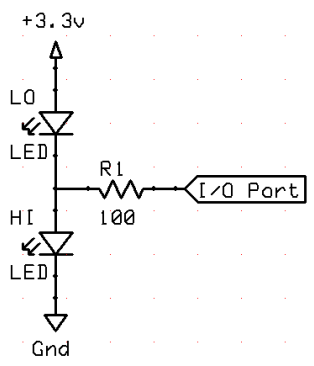
The circuit that will be used is that shown in Fig. 3-9 with I/O connected to
P4.
Fig 3-9 LED Status Indicator for Port Output HI or LO
Method presented in Project #4-4d where the delay Variables are declared as a Global Long sized Variables delayON and delayOFF, remains the same.
Click the link above to download the Spin Code listed below in .txt format
CON
        LED_Pin = 4
                  ' Identifying the Port to which LED is connected
VAR
        Long delayON   ' Declaration of delayON   Long variable
        Long delayOFF  ' Declaration of delayOFF  Long variable

PUB LedOn                       ' Method declaration
        delayON := 1_500        'in Milliseconds
        delayOFF := 500         'in Milliseconds
        dira[LED_Pin] ~~  'Set LED_Pin to output(Using Post-Set)
        repeat        ' Endless loop prevents program from ending
          outa[LED_Pin] ~~  ' Set P4 high(HI=ON)(Using Post-Set)
          waitcnt(((clkfreq/1_000)*delayON) + cnt) 'wait for delay

          outa[LED_Pin] ~ ' Set P4 low(LO=OFF)(Using Post-Clear)
          waitcnt(((clkfreq/1_000)*delayOFF) + cnt)'wait for delay
The circuit that is used as is shown in Fig. 3-9 with I/O connected to P4 has two LEDs, one Orange and one Green.
The Orange is
Sinked, that is it is ON when the P4 is LO (0 V) and the Green is
Sourced, that is it is ON when the P4 is HI (3.3V).
This circuit in Fig. 3-9 with I/O connected to P4 effectively provides
ON and OFF positive indication as well as “fail” state, since when the
P4 is not functioning as “output” and reverts to “input” it provides HI-Z impedance, which causes both LEDs to be ON at low intensity with the 3.3V power supply.
If the combined LED Forward Voltage (Vf) is higher than 3.3V then both LEDs will be OFF.
Project #4-5
LED on/off for specified time interval after switch activation - TIME DELAY - single shot (Positive Logic)
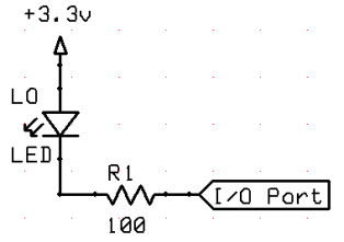
The circuit that will be used now is that shown in Fig. 3-7b with I/O connected to
P27.
Fig 3-7b LED Status Indicator for Port Output HI
The second circuit is that shown in Fig. 3-10 with I/O connected to
P10.
Click the link above to download the Spin Code listed below in .txt format
PUB singleshot

  dira[27] := 1              'sets P27 to output [LED]
  dira[10] := 0              'sets P10 to input [push button N/O]

  repeat               'Endless loop prevents program from ending
    if ina[10]              'If push button pressed continue code
      outa[27]~~                  'Set P27 HI = Turn LED ON
      waitcnt(clkfreq/2  +  cnt)  'Wait for specified time
      outa[27]~                   'Set P27 LO = Turn LED OFF
      if ina[10]      'If push button still pressed continue code
        repeat while ina[10]'Loop while push button is pressed
When P10 Push-button is pressed the LED on
P27 is turned on for a 1/2 second.
If the button is released sooner the LED is still on for only 1/2 second.
If the button is held for longer than 1/2 second the LED is still turned OFF after the 1/2 second interval and the repeat while loops indefinitely while the push-button is held closed.
When the push-button is released the program loops back to endless loop and tests for the push-button press in the if ina[10] statement.
This Method assures that the timed output event on Port P27 occurs only once per each Port
P10 input, irrespective of the input duration.
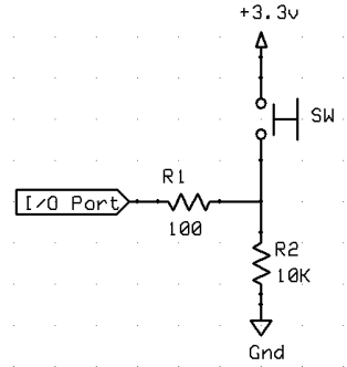
Positive Logic
Keep in mind that any device that will connect the Input Port to +3.3V (or even a higher voltage if the Port is protected with appropriate size resistor) can replace the Push-button.
It could be independent power source, as long as it shares a common Ground.
It could be transistor or FET, or any sensor that switches ON to provide +3.3V output.
It could be OptoIsolator, etc.
As long as the normal OFF condition is Ground on the Input Port and the normal
ON condition is +Voltage on the Input Port, this program will work properly.
When the signal, no matter how it is generated, is +Voltage above the Propeller sensing threshold of +1.65V (HI), it is referred to as "positive" logic.
The system is said to be ON when the signal is HI, and when it is
OFF the signal is LO, or below +1.65V, however generally it is preferable that it is 0V or Ground.
So in this program example (
4-5_singleshotSWP10-LEDP27.spin ) the normal continuous condition is
OFF (LO) because the potential on the P10 is Ground (through 10K Ohm resistor) and only when the Push-button is depressed the +3.3V signal (ON = HI) is applied to
P10.
The program then proceeds to turn the P27 LED ON (Output HI) for pre-programmed time interval, which in this case is 1/2 second or 500 milliseconds.
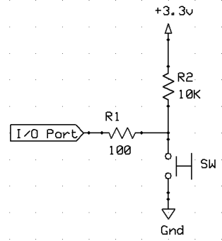
Negative Logic
When the normal steady state signal is +Voltage, but the system is considered to be in
OFF condition, and when it is activated by a 0V or Ground signal to be in the
ON condition, it is referred to as "Negative" logic.
This means that +Voltage (HI = OFF) and 0V or Ground (LO = ON).
Just a slight modification is required to the previous program to use "Negative" logic.
Project #4-5a
LED on/off for specified time interval after switch activation - TIME DELAY - single shot (Negative Logic)
The circuit that will be used now is that shown in Fig. 3-7b with I/O connected to
P27.
Fig 3-7b LED Status Indicator for Port Output HI
The second circuit is that shown in Fig. 3-11 with I/O connected to
P10.
Click the link above to download the Spin Code listed below in .txt format
'' File: 4-5a_ButtonP10ToLedP27TimedNL.spin

PUB singleshot

  dira[27] := 1               'Sets P27 to output [LED]
  dira[10] := 0               'sets P10 to input [push button N/O]

  repeat                'Endless loop prevents program from ending
    if ina[10] == 0'If push button pressed continue code(0V on P10)
      outa[27]~~                        'Set P27 HI = Turn LED ON
      waitcnt(clkfreq/2 + cnt)          'Wait for specified time
      outa[27]~                         'Set P27 LO = Turn LED OFF
      if ina[10] == 0  'If push button still pressed continue code
        repeat while ina[10] == 0'Loop while push button is pressed
It is preferable to define the Logic in a CONblock, that way is the triggering logic changed from Positive to Negative or the other way around, all you need to do is to change two statements in the
CON block and the program will work fine without any other modifications.
The ( 4-5a_ButtonP10ToLedP27TimedNLa.spin ) illustrates such program change.
Click the link above to download the Spin Code listed below in .txt format
'' File: 4-5a_ButtonP10ToLedP27TimedNLa.spin
CON
  HI = 0                            '  Define negative logic high
  LO = 1                            '  Define negative logic low

PUB singleshot
  dira[27] := 1              'Sets P27 to output [LED]
  dira[10] := 0              'sets P10 to input [push button N/O]

  repeat                'Endless loop prevents program from ending
    if ina[10] == HI
                  'If push button pressed continue code(0V on P10)
      outa[27]~~                        'Set P27 HI = Turn LED ON
      waitcnt(clkfreq/2 + cnt)          'Wait for specified time
      outa[27]~                         'Set P27 LO = Turn LED OFF
      if ina[10] == HI
                  'If push button still pressed continue code
        repeat while ina[10] == HI
                  'Loop while push button is pressed
Links to related Webpages
Click the link in the list below to navigate to a detailed webpage about the listed subject.