Parallax Propeller Book - Programming Part 2
Reading Inputs
Prerequisites:
- Completed Programming Part 1 (Chapter 4)
Equipment:
- Computer with Win 10 and all Set Up files already Installed
-
Propeller Activity Board (PAB)
or Propeller Microcontroller Module (FLiP) -
USB Cable to connect PAB to Computer (USB to USB mini-B)
or for FLiP (USB to USB micro-B connector) - Propeller Tool installed on Computer
Components:
- Resistor - 100 Ohm 1/4 W
- Resistor - 10K Ohm 1/4 W
- Switch - Push Button - Normally OFF = N/O
- LED Yellow
- LED Red
- Jumper - M/M 50mm (2") AWG24 Yellow
- Jumper - M/M 50mm (2") AWG24 Black
- Jumper - M/M 50mm (2") AWG24 Red
- Jumper - M/M 75mm (3") AWG24 Green
- Breadboard, with Power Strips (only if FLiP is used)
Objective:
- Read Switch State (ON or OFF) – detecting I/O port status (HI or LO)
- Conditional Control of LED on/off – Turn LED ON or OFF depending on status of the I/O port (HI or LO)
Reading Switches
Reading Pull UP Switch
Project #4.2-1
Reading Input, controlling Output
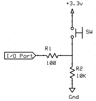
To read the Input of P10 we will use the circuit in Figure 3-10.
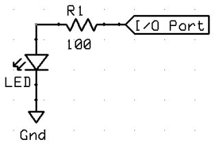
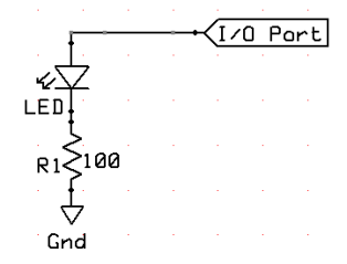
To control the Output on P26 we will use the circuit in Figure 3-7a or in Figure 3-7b.
The ina register is a Read-Only register in Cog RAM whose bits store the voltage state of each I/O pin.
When an I/O pin is set to output, its ina register bit will report the same value as the outa register bit since ina bits indicate high/low I/O pin voltages with 1 and 0.
If the I/O pin is instead an input, its ina register bit updates based on the voltage applied to it.
If a voltage above the I/O pin’s 1.65 V logic threshold is applied, the ina register bit stores a 1; otherwise, it stores a 0.
The ina register is updated with the voltage states of the I/O pins each time an ina command is issued to read this register.
The push-button connected to P10 will apply 3.3 V to P10 when pressed, or 0 V when not pressed.
In the ButtonToLed object below, dira[10] is set to 0, making I/O pin P10 function as an input.
So, it will store 1 if the P10 push-button is pressed, or 0 if it is not pressed.
By repeatedly assigning the value stored in ina[10] to outa[26], the ButtonLed method makes the P26 LED light whenever the P10 push-button is pressed.
Notice also that the command outa[26] := ina[10] is indented below the repeat command, which causes this line to get executed over and over again indefinitely.
Click the link above to download the Spin Code listed below in .txt format
'' 4.2-1_ButtonP10ToLedP26.spin
'' LED mirrors push-button state.
'' Project #4.2-1 Reading Input, controlling Output

PUB ButtonLed 			'Push-button/Led Method

dira[26] := 1 		' P26 → output
dira[10] := 0 		' P10 → input (this command is redundant)

repeat 			' endlessly loop code below
	outa[26] := ina[10]
                ' Copy P10 input (push-button) to P26 output (LED)
Reading Pull DOWN Switch
Project #4.2-2
Reading Input, controlling Output
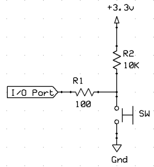
To read the Input of P11 we will use the circuit in Figure 3-11.
To control the Output on P26 we will use the circuit in Figure 3-7a or in Figure 3-7b.
The ina register is a Read-Only register in Cog RAM whose bits store the voltage state of each I/O pin.
When an I/O pin is set to output, its ina register bit will report the same value as the outa register bit since ina bits indicate high/low I/O pin voltages with 1 and 0.
If the I/O pin is instead an input, its ina register bit updates based on the voltage applied to it.
If a voltage above the I/O pin’s 1.65 V logic threshold is applied, the ina register bit stores a 1; otherwise, it stores a 0.
The ina register is updated with the voltage states of the I/O pins each time an ina command is issued to read this register.
The push-button connected to P11 will apply 0 V to P11 when pressed, or 3.3 V when not pressed.
In the ButtonToLed object below, dira[11] is set to 0, making I/O pin P11 function as an input. So, it will store 0 if the P11 push-button is pressed, or 1 if it is not pressed.
By repeatedly assigning the value stored in ina[11] to outa[26], the ButtonLed method makes the P26 LED light whenever the P11 push-button is NOT pressed.
Notice also that the command outa[26] := ina[11] is indented below the repeat command, which causes this line to get executed over and over again indefinitely.
Click the link above to download the Spin Code listed below in .txt format
'' 4.2-2_ButtonP11ToLedP26.spin
'' Led mirrors pushbutton state.
'' Project #4.2-2 Reading Input, controlling Output

PUB ButtonLed 			'Pushbutton/Led Method

dira[26] := 1 		' P26 → output
dira[11] := 0 		' P11 → input (this command is redundant)

repeat 				' Endlessly loop code below
	outa[26] := ina[11] 	' Copy P11 input to P26 output
Spinning Spin
Another way to copy input to output.
Using The Bitwise NOT - “!”
• Replace this:
outa[26] := ina[11]
• ... with this:
outa[26] := !ina[11]
This will reverse the button functionality to LED ON when button is pressed.
Reading Signals
Reading Ground Signal
Project #4.2-3
Reading Input, controlling Output
To read the Input on P15 we will use the circuit in Figure 3-11.
Note: The "SW" can be any device that provides Ground Signal to the
P15 port.
To control the Output on P27 we will use the circuit in Figure 3-7a or in Figure 3-7b.
The ina register is a Read-Only register in Cog RAM whose bits store the voltage state of each I/O pin.
When an I/O pin is set to output, its ina register bit will report the same value as the outa register bit since ina bits indicate high/low I/O pin voltages with 1 and 0.
If the I/O pin is instead an input, its ina register bit updates based on the voltage applied to it.
If a voltage above the I/O pin’s 1.65 V logic threshold is applied, the ina register bit stores a 1; otherwise, it stores a 0.
The ina register is updated with the voltage states of the I/O pins each time an ina command is issued to read this register. The signal applied to P15 will apply 0 V to P15 when "ON" , or 3.3 V when "OFF".
In the singleshot object below, dira[15] is set to 0, making I/O pin P15 function as an input. So, it will store 0 if the P15 Ground signal is present, or 1 if it is not present, that is P15 is HI.
The singleshot method makes the P27 LED light for specified time interval (1/2 second) whenever the P15 Ground signal is present for any duration.
Notice also that the command repeat while ina[15] == 0 is indented below the if ina[15] == 0 command, which causes this line to get executed over and over again indefinitely if the Ground signal is still present.
This results in a "single shot" of the output per each Ground input signal, irrespective of the Ground signal duration.
4.2-3_GSignalP15ToLedP27Timed.spin
Click the link above to download the Spin Code listed below in .txt format
'' 4.2-3_GSignalP15ToLedP27Timed.spin

PUB singleshot

  dira[27] := 1                      'Sets P27 to output [LED]
  dira[15] := 0                      'sets P15 to input
				' [external signal 0V=ON  3.3V=OFF]

  repeat              'Endless loop prevents program from ending
    if ina[15] == 0        'If GND signal present continue code
      outa[27]~~                  'Set P27 HI = Turn LED ON
      waitcnt(clkfreq/2 + cnt)'Wait for specified time(1/2 second)
      outa[27]~                   'Set P27 LO = Turn LED OFF
      if ina[15] == 0
                    'If GND signal is still present continue code
        repeat while ina[15] == 0
                    'Loop while GND signal is still present
Links to related Webpages
Click the link in the list below to navigate to a detailed webpage about the listed subject.
- PREVIOUS:
Parallax Propeller Book - Chapter 2 (Definitions)
- PREVIOUS:
Parallax Propeller Book - Chapter 3 (Components)
- PREVIOUS:
Parallax Propeller Book - Chapter 4 Part 1 (Programming:
Controlling Outputs)
- NEXT:
Parallax Propeller Book - Chapter 4 Part 3 (Programming:
Spin Programming)