Parallax Propeller Book - Components
This chapter describes some of the components that are necessary to make a complete working System that uses the PARALLAX Propeller microcontroller.
If you are using any of the Propeller Boards, you can skip this
chapter as all the components
that are needed are already preinstalled on those Boards.
However it helps to understand how the entire system works if you know what the individual components are.
Propeller (Parallax) Power System
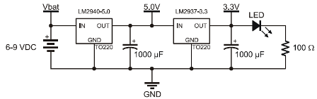
5V Regulator (Parallax)
The National Semiconductor LM2940CT-5.0 Regulator is included in the PEK Platform to make it convenient to supply 5 V to some components, such as the infrared detector introduced in the Counter Modules and Circuit Applications Labs.
A series resistor (typically 10 kΩ) should always be connected between a 5 V output and a Propeller I/O Port pin, which is 3.3 V.
The 5 V regulator also serves as an intermediate stage between the battery input voltage and the 3.3 V regulator that supplies the Propeller chip.
The LM2940 voltage regulator circuit is designed to provide a 400 mA output current budget with a 9V battery supply in the classroom or lab (at room temperature).
This current budget can vary with supply voltage and temperature. For example, if the supply voltage reduced from 9 V to 7.5 V, the current budget increases to nearly 700 mA at room temperature. Another example, if the supply voltage is 9 V, but the ambient temperature is 100 °F (40 °C), the current budget drops to around 350 mA.
3.3V Regulator (Parallax)
This National Semiconductor LM2937ET-3.3 regulator can draw up to 400 mA from the LM2940 (5 V regulator) at room temperature and supply the 3.3 V system with up to 360 mA of current.
The 3.3 VDC system includes the Propeller chip, EEPROM, and LED Power Indicator.
The +3.3V is connected to the Propeller chip Pins 12 and 32 (Vdd) the Ground is connected to Pins 9 and 29 (Vss) and also to Pin 10 (BOEn).
LED Power Indicator
About 12 to 13 mA power consumption at 3.3V or less than 17 mW.
Click on the image below to see larger image
System Timing Oscillators
5.00 MHz Crystal Oscillator
The 5.00 MHz Crystal Oscillator provides the Propeller chip with a precise clock signal that can be used for time-sensitive applications such as Serial communication, RC decay measurements and Servo control.
The Propeller chip has built-in phase locked loop circuitry that can use the 5.00 MHz oscillator signal to generate system clock frequencies of 5, 10, 40 or 80 MHz.
The 80 MHz setting provides for the fastest possible code execution, while the 5 MHz setting will use the least amount of power.
Low power consumption is preferable for battery operated devices where the execution speed is not critical.
Crystal Oscillator is connected to the Propeller chip Pin 30 (XI) and Pin 31 (XO).
Built-In Oscillator
The Propeller chip also has a built-in RC oscillator that can be used in fast or slow modes (approximately 12 MHz and 20 kHz respectively).
The internal Oscillators are not precise.
Therefore there two modes should be only used in applications where precision timing is not required.
Memory
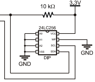
32 KB EEPROM
32 KB EEPROM program and data storage memory is non-volatile, meaning it can’t be erased by pressing and releasing the reset button or disconnecting and reconnecting power.
[EEPROM: Electrically Erasable Programmable Read-Only Memory]
This EEPROM memory should not be treated like RAM because each of its memory cells is only good for 1 million erase/write cycles.
After that, the cell can actually wear out and no longer reliably store values.
Program that modifies an EEPROM cell once every second would wear it out in only 11.6 days. On the other hand, if a cell gets modified every ten minutes, it will be good for over 19 years. 24LC256-DIP8 EEPROM chip is used in the System and is connected as follows:
| Pin ID | Propeller Pin (Port) | Function |
|---|---|---|
| 1 - A0 | Ground | |
| 2 - A1 | Ground | |
| 3 - A2 | Ground | |
| 4 - Vss | Ground | |
| 5 - SDA | 38 (P29) via 10K | SDA |
| 6 - SCL | 37 (P28) | SCL |
| 7 - WP | Ground | |
| 8 - Vcc | 38 (P29) | +3.3VDC |
Communication
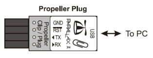
Propeller Plug (USB)
The Propeller Plug is used to communicate with PC (Windows) and to load programs to the Propeller RAM or to the System EEPROM.
It is wired to the Propeller chip as follows:
| Propeller Plug Pin – Pin ID | Propeller Pin (Port) | Function |
|---|---|---|
| 1 - GND | 9 (Vss) and 10 (BOEn) |
Ground |
| 2 - RES | 11 (RESn) | Reset if Grounded |
| 3 – TX > RX | 40 (P31) | Serial Communication |
| 3 – RX < TX | 39 (P30) | Serial Communication |
LED Status Indicator(s)
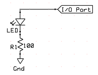
Port Output HI
I/O Pin
Resistor (R1) – 100 Ω (brown-black-brown) * or any value up to 470 Ω (yellow-purple-brown)
LED
Ground
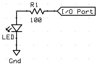
FUNCTION:
- The I/O Port set as OUTPUT (1) and it has 3.3V present on it (HI); LED is ON.
- The I/O Port set as OUTPUT (0) and it has GND present on it (LO); LED is OFF.
- The I/O Port set as INPUT and it has Hi-Z present on it; LED is OFF.
POWER through R1 and LED
E = Vcc - Vf System Voltage (Vcc) minus Diode Forward Voltage (Vf) drop
3.3-2=1.3 V
I = E / R LED Circuit Current (I)
1.3/100=0.013 A
0.013*1,000=13.0 mA
Since the Propeller chips I/O Port is limited to maximum power source of 40 mA and the 13 mA is well below that limit, this circuit can be connected safely to any Port.
P = I * E LED Circuit Power (P) Consumption
0.013*1.3=0.0169 W
0.0169*1,000=16.9 mW
NOTE:
To reduce power consumption, resistor as high as 470 Ohm can be used.
This circuit with R1 = 240 Ohm is used on Propeller Activity Board (PAB) on P26 and P27.
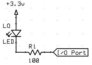
Port Output HI - alternate
I/O Pin
Resistor (R1) – 100 Ω (brown-black-brown) * or any value up to 470 Ω (yellow-purple-brown)
LED
Ground
FUNCTION:
- The I/O Port set as OUTPUT (1) and it has 3.3V present on it (HI); LED is ON.
- The I/O Port set as OUTPUT (0) and it has GND present on it (LO); LED is OFF.
- The I/O Port set as INPUT and it has Hi-Z present on it; LED is OFF.
POWER through R1 and LED
E = Vcc - Vf System Voltage (Vcc) minus Diode Forward Voltage (Vf) drop
3.3-2=1.3 V
I = E / R LED Circuit Current (I)
1.3/100=0.013 A
0.013*1,000=13.0 mA
Since the Propeller chips I/O Port is limited to maximum power source of 40 mA and the 13 mA is well below that limit, this circuit can be connected safely to any Port.
P = I * E LED Circuit Power (P) Consumption
0.013*1.3=0.0169 W
0.0169*1,000=16.9 mW
NOTE:
To reduce power consumption, resistor as high as 470 Ohm can be used.
This circuit with R1 = 470 Ohm is used on Propeller Professional Development Board (PRO) for all indicator LEDs.
Port Output LO
I/O Pin
Resistor (R1) – 100 Ω (brown-black-brown) * or any value up to 470 Ω (yellow-purple-brown)
LED
Ground
FUNCTION:
- The I/O Port set as OUTPUT (1) and it has 3.3V present on it (HI); LED is OFF.
- The I/O Port set as OUTPUT (0) and it has GND present on it (LO); LED is ON.
- The I/O Port set as INPUT and it has Hi-Z present on it; LED is OFF.
POWER through R1 and LED
E = Vcc - Vf System Voltage (Vcc) minus Diode Forward Voltage (Vf) drop
3.3-2=1.3 V
I = E / R LED Circuit Current (I)
1.3/100=0.013 A
0.013*1,000=13.0 mA
Since the Propeller chips I/O Port is limited to maximum power source of 40 mA and the 13 mA is well below that limit, this circuit can be connected safely to any Port.
P = I * E LED Circuit Power (P) Consumption
0.013*1.3=0.0169 W
0.0169*1,000=16.9 mW
NOTE:
To reduce power consumption, resistor as high as 470 Ohm can be used.
Port Status = Output HI or LO; Input
I/O Pin
Resistor (R1) – 100 Ω (brown-black-brown) * or any value up to 470 Ω (yellow-purple-brown)
LED Orange (HI)
LED Blue (LO)
Ground
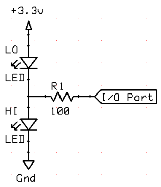
FUNCTION:
-
The I/O Port set as OUTPUT (1) and it has +3.3V present on it (HI);
HI LED (Orange) is ON, LO LED (Blue) is OFF. -
The I/O Port set as OUTPUT (0) and it has 0V present on it (LO);
LO LED (Blue) is ON, HI LED (Orange) is OFF. -
The I/O Port set as INPUT and has Hi Z present on it (Z);
Both LEDs are OFF as their combined Forward Voltage Vf (2+2=4V) exceeds the Vcc (+3.3V).
However with LEDs that have lower combined Forward Voltage Vf, they may be ON at low intensity.
POWER through R1 and LED
E = Vcc - Vf System Voltage (Vcc) minus Diode Forward Voltage (Vf) drop
3.3-2=1.3 V
I = E / R LED Circuit Current (I)
1.3/100=0.013 A
0.013*1,000=13.0 mA
Since the Propeller chips I/O Port is limited to maximum power source of 40 mA and the 13 mA is well below that limit, this circuit can be connected safely to any Port.
P = I * E LED Circuit Power (P) Consumption
0.013*1.3=0.0169 W
0.0169*1,000=16.9 mW
NOTE:
To reduce power consumption, resistor as high as 470 Ohm can be used.
LED Color Scheme
In the projects in following chapters when it is possible following LED color scheme will be used:
| LED Color | Voltage | State |
|---|---|---|
| Yellow | +12VDC | ON |
| Red | +5VDC | ON |
| Amber | +3.3VDC | ON |
| Blue | GND | |
| Green | Switched Low Current Signal | ON |
| White | Switched High Current Load | ON |
Switches
Switch - Pull Down R
Resistor (R1) – 100 Ω (brown-black-brown) or 120 Ω (brown-red-brown) or 150 Ω (brown-green-brown)
Resistor (R2) – 10 kΩ (brown-black-orange)
Push-button (SW)
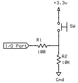
FUNCTION:
- The I/O Port set as INPUT has Ground present on it (LO) via R2 10K Ohm resistor and 100 Ohm resistor.
- When the Switch is CLOSED the Port is connected to +3.3V (HI) via 100 Ohm resistor.
POWER through R2
I = E/R
3.3/10,000=0.0003 A
0.0003*1,000=0.3 mA
P = I*E
0.0003*3.3=0.001 W
0.001*1,000=1.0 mW
Switch - Pull Down R+C
Resistor (R1) – 10 kΩ (brown-black-orange)
Resistor (R2) – 100 Ω (brown-black-brown) or 120 Ω (brown-red-brown) or 150 Ω (brown-green-brown)
Push-button (S1)
Capacitor (C1) - 100nF = 0.1µF
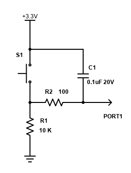
FUNCTION:
- The I/O Port set as INPUT has Ground present on it (LO) via R1 10K Ohm resistor and R2 100 Ohm resistor.
- When the Switch is CLOSED the Port is connected to +3.3V (HI) via R2 100 Ohm resistor.
POWER through R1
I = E/R
3.3/10,000=0.0003 A
0.0003*1,000=0.3 mA
P = I*E
0.0003*3.3=0.001 W
0.001*1,000=1.0 mW
The C1 100 nF Capacitor helps to reduce false triggering due to switch bounce, should that be a problem in your particular application.
While we use low cost ceramic capacitor, you can try other non-polarized capacitors, ranging in values from 10nF to 500nF.
If false triggering is still a problem then more sophisticated circuit with Schmitt Trigger IC would need to be utilized.
Schmitt trigger is a comparator circuit with hysteresis implemented by applying positive feedback to the non-inverting input of a comparator or differential amplifier. It is an active circuit which converts an analog input signal to a digital output signal.
Switch - Pull Up R
Resistor (R1) – 100 Ω (brown-black-brown) or 120 Ω (brown-red-brown) or 150 Ω (brown-green-brown)
Resistor (R2) – 10 kΩ (brown-black-orange)
Push-button (SW)
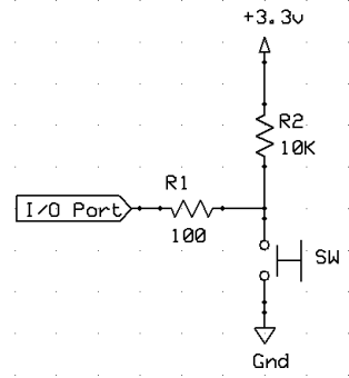
FUNCTION:
- The I/O Port set as INPUT has +3.3V (HI) present on it via R2 10K Ohm resistor and 100 Ohm resistor.
- When the Switch is CLOSED the Port is connected to Ground (LO) via 100 Ohm resistor.
POWER through R2
I = E/R
3.3/10,000=0.0003 A
0.0003*1,000=0.3 mA
P = I*E
0.0003*3.3=0.001 W
0.001*1,000=1.0 mW
NOTE:
This circuit with R1 = 150 Ohm is used on Propeller Pro Board
Switch - Pull Up R + C
Resistor (R1) – 10 kΩ (brown-black-orange)
Resistor (R2) – 100 Ω (brown-black-brown) or 120 Ω (brown-red-brown) or 150 Ω (brown-green-brown)
Push-button (S1)
Capacitor (C1) - 100nF = 0.1µF
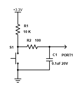
FUNCTION:
- The I/O Port set as INPUT has +3.3V (HI) present on it via R1 10K Ohm resistor and R2 100 Ohm resistor.
- When the Switch is CLOSED the Port is connected to Ground (LO) via R2 100 Ohm resistor.
POWER through R1
I = E/R
3.3/10,000=0.0003 A
0.0003*1,000=0.3 mA
P = I*E
0.0003*3.3=0.001 W
0.001*1,000=1.0 mW
The C1 100 nF Capacitor helps to reduce false triggering due to switch bounce, should that be a problem in your particular application.
While we use low cost ceramic capacitor, you can try other non-polarized capacitors, ranging in values from 10nF to 500nF.
If false triggering is still a problem then more sophisticated circuit with Schmitt Trigger IC would need to be utilized.
RC Decay Circuit
Resistor (R1) – 100 Ω (brown-black-brown)
Potentiometer (R2) – 5 kΩ (slide linear)
Capacitor 0.01μF = 10nF (C1)
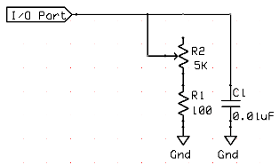
FUNCTION:
- The I/O Port set as OUTPUT (1) and set to (1) so it has +3.3V present on it (HI).
- The C1 is charged to +3.3V after some time.
- The I/O Port is set to INPUT (0) and Timer is started.
- When the INPUT initially (1) (HI) drops below +1.65V (Vcc/2) the INPUT is set to (0) and Timer is stopped; then the R2 value is calculated by the microcontroller software.
![]()
Currently this page is still under development, so please check back periodically for new links to pages as we add them to this list.
Links to related Webpages
Click the link in the list below to navigate to a detailed webpage about the listed subject.
- PREVIOUS:
Parallax Propeller Book - Chapter 2 (Definitions)
- NEXT: Parallax Propeller Book - Chapter 4 (Programming)