Parallax Propeller Book - Basics
Propeller
Propeller microcontroller is a single chip with eight built-in 32-bit processors, called Cogs.
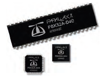
Propeller micro-controllers are available from PARALLAX in 40-pin DIP, TSOP and QFN packages as well as pre-installed on number of boards.
[bit: is the basic unit of information in computing and digital communications. A bit can have only one of two values, and may therefore be physically implemented with a two-state device. These values are most commonly represented as either a 0 or 1. The two values can also be interpreted as logical values (true/false, yes/no), algebraic sign (+/−), activation states (on/off), voltage (HI/LO), or any other two-valued attribute.]
[32-bit: Computers, operating systems, or software programs capable of transferring data 32-bits at a time, that is any information that can be represented from "00000000000000000000000000000000" representing a decimal number "0" (zero) to "11111111111111111111111111111111" representing a decimal number up to 4,294,967,295.
Computer processors, (e.g. 80386, 80486, and Pentium) are 32-bit processors, which means the processor is capable of working with 32 bit binary numbers (decimal number up to 4,294,967,295). Anything larger and the computer software needs to break up the number into smaller pieces.
32 KB of the Propeller chip’s main memory is RAM used for program and data storage.
[KB or kB: One thousand bytes. In computing and storage systems, a kB (kiloByte) is actually 1,024 (210) bytes, since the measurement is based on a base 2, or binary, number system. The term kB comes from the fact that 1,024 is nominally, or approximately, 1,000.]
[byte: is a unit of digital information that most commonly consists of eight bits. It can represent numbers from 0 to 255.]
[RAM = Random Access Memory]
Another 32 KB is ROM, and stores useful tables such as log, anti-log, sine, and graphic character tables. The ROM also stores boot loader code that Cog0 uses at start-up and interpreter code that any Cog can use to fetch and execute Application code from main memory.
[ROM = Read Only Memory] Each Cog also has the ability to read the states of any or all of the Propeller chip’s 32 I/O Ports at any time, as well as set their directions (Input or Output) and Output or Input states (HI or LO) at any time.
[I/O = Input and/or Output]
[Note: applicable to Propeller chip:
HI = is any voltage above 1.65V and up to 3.3V = chip supply Voltage
LO = is any voltage between 0V = Ground and 1.65V]
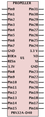
I / O Ports (Pins)
In this e-book we will refer to the I/O connections as Ports, however be aware that in may other publications the I/O connections are referred to as Pins.
The reason we do this is to separate the programming address of the Port from the physical location of the mechanical Pin, to which the electronic circuit is connected.
For example:
The Propeller 40 pin chip has the Port "0" (zero) on the mechanical Pin #1.
To avoid confusion in the Spin programs the code controlled Ports will be referred to as "P".
For example:
The Propeller 40 pin chip Port "0" (zero) on the mechanical Pin #1 will be
P0.
In this e-book we will refer to the tri-state connections to the Propeller chip as Ports, and the actual mechanical connections as Pins.
In the program code the 32 available Ports will be labeled as P0 to P31.
In some of the PARALLAX documentation the Ports are referred to as Pins, but that may be confusing to the novice, as the “Pin” does not mechanically correspond to the connection to the Propeller micro-controller chip.
In Figure 1-2 you can see that the “Port0” labeled as “Pin0” which is P0 in the Spin code, is actually the mechanical “Pin #1" (Top Left) and the “Port31” labeled as “Pin31” which is P31 in the Spin code, is actually the mechanical “Pin #40" (Top Right).
Tri-State
Tri-State or Three State - An output from a logic device that can exist in one of three states:
- logic 0 (zero)
- logic 1 (one)
- high-impedance (disconnected) state
This “third” state allows multiple outputs to connect to one signal, effectively providing a "bus" that many signals can share.
Tri-state devices will provide an output-enable signal that either connects logic signals to the device’s outputs, or places the outputs in a high-impedance state.
(National Semiconductor owns the trademark, "tristate™," although the term finds common use among designers.)
In relationship to the Propeller Input / Output Ports (I/O) the three states are:
- OUTPUT HI = +3.3 VDC is applied to the Port = chip's power supply Voltage
- OUTPUT LO = 0 VDC or Ground applied to the Port
- INPUT (Hi-Z) = High-impedance if considered as “Output”, but as “Input” it senses the Voltage applied to this Port. If the voltage is above the 1.65V threshold, the Input is considered to be HI and if it is below that threshold, it is considered to be LO.
Cogs
Cog is a processor inside the Propeller chip.
The Propeller chip has eight Cogs, making it possible to perform lots of tasks in parallel.
The Propeller chip’s eight Cogs are numbered Cog0 through Cog7.
The Propeller is like a super-micro-controller with eight high speed 32-bit processors inside.
Each internal processor (Cog) has access to all of the Propeller chip’s I/O pins and 32 KB of Global RAM.
Each Cog also has its own 2 KB of RAM that can either run a Spin code interpreter or an assembly language program.
Cogs can be programmed to function simultaneously, both independently and cooperatively with other Cogs. In other words, Cogs can all function simultaneously, but whether they function independently or cooperatively is defined by the program.
Groups of Cogs can be programmed to work together, while others work on independent tasks.
System Clock
Configurable system clock supplies all the Cogs with the same clock signal (up to 80 MHz).
Figure 1-3 shows how each Cog takes turns at the option for exclusive read/write access of the Propeller chip’s main memory via the Hub.
Exclusive read/write access is important because it means that two Cogs cannot try to modify the same item in memory at the same instance. It also prevents one Cog from reading a particular address in memory at the same time another Cog is writing to it. Exclusive access ensures that there are never any memory access conflicts that could corrupt data.
Timing
Hub grants main memory access to each Cog every 16 clock cycles. (200 ns @ 80 MHz).
[ ns = nanosecond is an SI unit of time equal to one billionth of a second (10−9 or 1/1,000,000,000s) ]
[ MHz = Mega-Hertz = One million cycles per second. It is used to measure the transmission speed of electronic devices, including channels, buses and the computer's internal clock. A one Mega-Hertz clock (1MHz) means some number of bits (1, 4, 8, 16, 32 or 64) can be manipulated at least one million times per second ]
Depending on when the Cog decides to check with main memory, the access time could take anywhere from 7 to 22 clock cycles, which equates to a worst case memory access time of 275 ns @ 80 MHz. Loading programs into EEPROM takes a few seconds (under 10 seconds for most).
[EEPROM: Electrically Erasable Programmable Read-Only Memory]
Cog RAM not used by machine instructions can also provide high speed memory for the Cog with four clock cycles (50 ns @ 80 MHz) per read/write.
[RAM: Random Access Memory]
Links to related Webpages
Click the link in the list below to navigate to a detailed webpage about the listed subject.
- PREVIOUS: Parallax Propeller Book - Chapter 0 (Set-Up)
- NEXT: Parallax Propeller Book - Chapter 2 (Definitions)